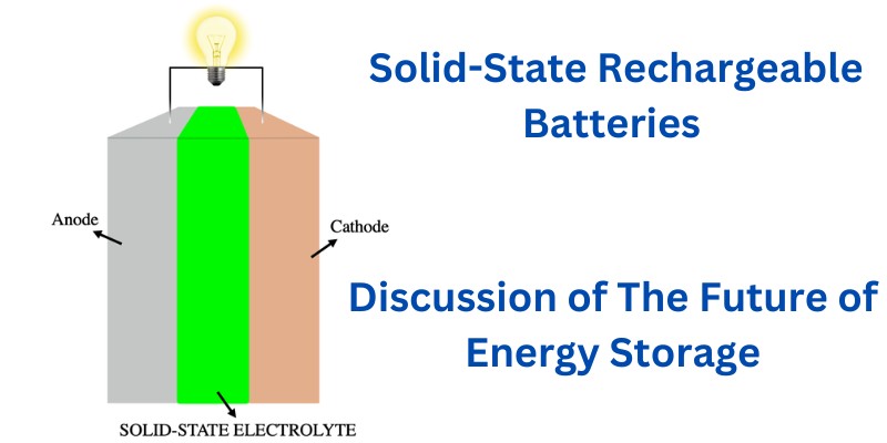
Solid-state rechargeable batteries are still under research and development but they represent a significant innovation in future energy storage technology. Image Source: By Luca Bertoli – Own work, CC BY-SA 4.0 Characterized by their use of solid electrolytes rather than the liquid or gel forms found in conventional batteries, they offer advancements in safety and […]
Is 32GB RAM Overkill for a Laptop Computer? Let’s Compare With 8GB and 16GB
There was a time when RAM was one of the most important selling points for most computing devices. Every memory upgrade in the microcomputer space opened up new possibilities for what users could do with them. The introduction of new software applications opened up new possibilities. Games, word processing, spreadsheets, databases, and more went from […]
Latest AI News Across the Web in April 2024

Here are some Artificial Intelligence (AI) News as of April 2024 that we have found interesting across the Web. Proposed Legislation Requires AI Firms to Disclose Utilization of Copyrighted Artwork Source: Key Takeaway The Generative AI Copyright Disclosure Act proposed by Congressman Adam Schiff aims to hold AI companies accountable for using copyrighted content by […]
22 Apps Like Grain – Get Line of Credit without Credit Score
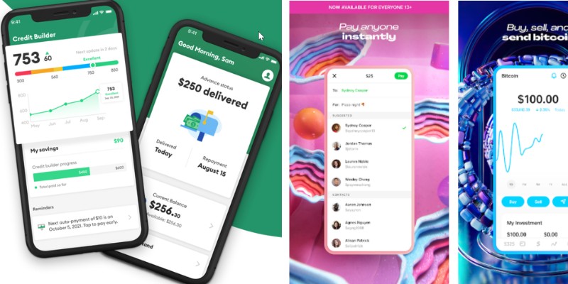
Not everyone has a credit score. In fact, everyone starts without one! But how can you build a credit score if everything that lets you build a credit score also requires a credit score? It’s simple. Apps like Grain make it possible to get a line of credit without a credit score, although there may be some caveats and […]
Advantages and Disadvantages of Xiaomi HyperOS: An In-Depth Analysis
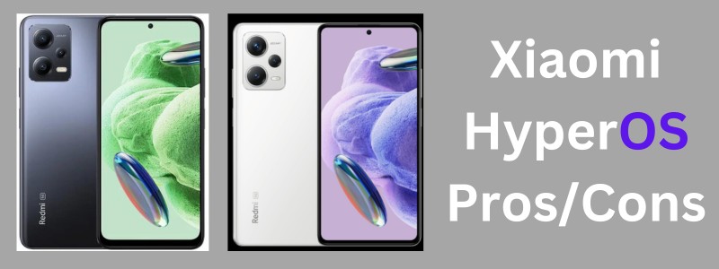
Xiaomi’s HyperOS emerges as a fresh contender in the tech giant’s ecosystem, aiming to elevate the user experience by introducing a human-centric design philosophy. This new operating system is inherently different from its predecessor, MIUI, sporting vibrant, dynamic animations and a user interface that feels more engaging. Your interactions with Xiaomi devices are set to […]
21 Sites and Apps Like Mercari for Buying/Selling Anything Online
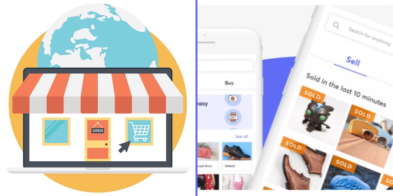
Digital marketplaces have become so popular in recent years because of their convenience and that it bypasses a lot of otherwise cumbersome processes of face to face transactions. You may call it the modern department store if you will. The marketplace doesn’t have to own anything that is put up on their site or application […]
26 Pros and Cons of Technology in 21st Century – What are the Benefits and Drawbacks?

“Technology” is defined by the Cambridge Dictionary as “the study and knowledge of the practical, especially industrial, use of scientific discoveries.” In this broad definition, technology encompasses everything from the use of primitive tools for hunting in ancient history to the cutting-edge smartphones we have today; technology is as old as civilization itself. In today’s […]
12 Advantages and Disadvantages of Allowing Cell Phones in Schools

Should cell phones be allowed in schools? It’s a hot debate to dial into if you’re a parent, teacher, or student. The truth is that cell phones already are in most schools so in this article we’ll explore the pros and cons of such fact and also discuss some important statistics and research on the […]
15 Different Types of Storage Devices and Disk Drives Used in Computer Systems
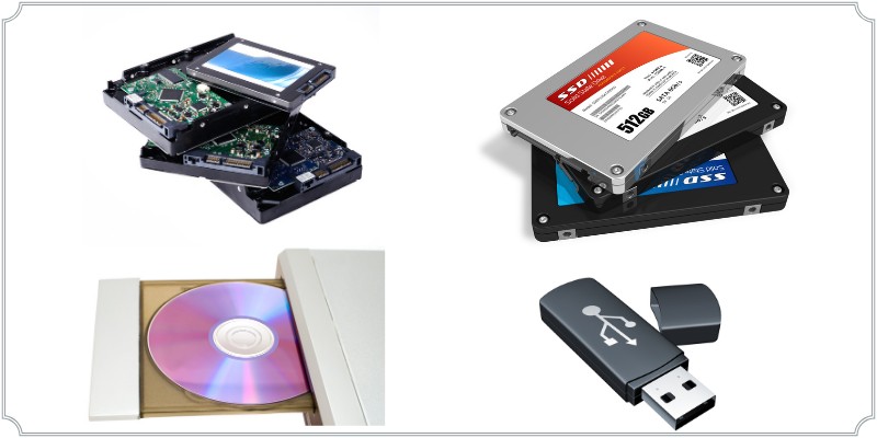
Computers utilize a variety of storage devices and media in order to read and write data. Without permanent or temporary storage, a computer wouldn’t function as expected. Most machines would be completely useless without a place to store digital data. Everything from the operating system to programs and individual files exist on storage after all. […]
20 Sites Like Afterpay – Competitor Companies & Alternatives for Shopping on Credit

It’s hard to believe that buying products online was once regarded very warily by a majority of people. In the years since the invention of the web, more and more people have enjoyed the diversity and convenience that online shopping offers them. Afterpay takes it one step further by offering consumers a way to purchase […]