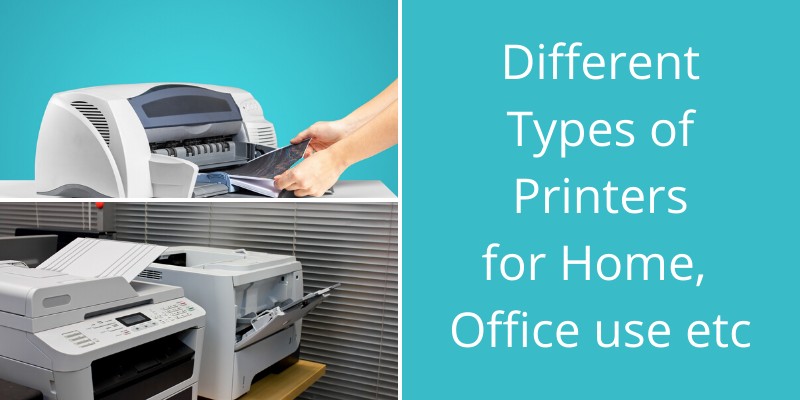
It isn’t hard to feel overwhelmed when looking at all the different types of printers on the market today. You’ve got “basic” inkjet style printers than most are familiar with, more advanced laser jet printers, all-in-one and multifunction systems, and then you start to dive into the more “specialty” printers available today – solid ink, […]
15 Best Free Music Player Software Apps for Windows 10

Our online lives are all about the consumption of media. The advent of the MP3 ushered in a revolution in the way that we listen to and consume music, and streaming music is now so commonplace that we all need a great music player application. So, here are the 10 best music players apps for […]
Metro Video Games in Order of Chronological Release (Main Titles)
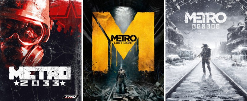
Welcome to our chronological order and guide about Metro video games. This game franchise is based on the novel by Dmitry Glukhovsky, which was published in 2005. A sequel was published in 2009 entitled Metro 2034, while the final book of the trilogy came in 2015 (Metro 2035). It tells a very dark story of […]
17 Best Email Client Apps for Windows 10 (Free and Paid)
Email is one of the the most popular forms of communication in the business world. Although new communication channels have emerged (such as collaboration apps, cloud communication web apps, VoIP and texting systems, instant messaging etc), email is still dominating although it is one of the oldest techs in the communication space. In this article […]
Nextiva Review for Small and Medium Business Communication Needs
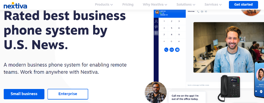
Remember the big and bulky old phone systems that once filled offices around the country? They took up space, they were expensive and required a telecom expert to configure and manage them. Thankfully, cloud services and virtualization came along the way, and many of those legacy systems were evolved as well and moved to the […]
6 Best Mechanical Gaming Keyboards – Buying Guide
Are you yet another gameaholic out there? Just like your games, the keyboard you use to play is definitely of huge importance to you. Moreover, there are many premium quality gaming mechanical keyboards out there and also some pretty bad ones which have spongy keys and features. Hence, you need to understand which one is […]
12 Tomb Raider Video Games in Order of Chronological Release (Main Titles)
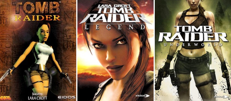
Tomb Raider or Lara Croft: Tomb Raider is a franchise that originally released in 1996. It was at this point where the original Tomb Raider video game was released on Sony’s PlayStation, Sega Saturn, and the PC. The franchise is known to be an action-adventure game that features a female protagonist known as Laura Croft. […]
Top Cybersecurity Mistakes Remote Workers Make

In February 2020, 4.7 million U.S. workers were working remotely according to statistics by Flexjobs. That is over 3.4 percent of the American working population — a number that has spiked dramatically over the last few months. With companies now being faced with the very real task of transferring its work environment into a remote working set-up, […]
How Are Cyber Security Teams Planning for the Future?

If anyone thought that security professionals were nonessential personnel, they’ve been roundly disabused by this pandemic. When our fraught schedules have allowed it, I’ve been having snippets of conversations with colleagues who manage security departments in various industries all over the world. These men and women are wading in alligators up to their, ahem, access: […]
Top 10 Kingdom Hearts Games Ranked from Worst to Best (2021 List)
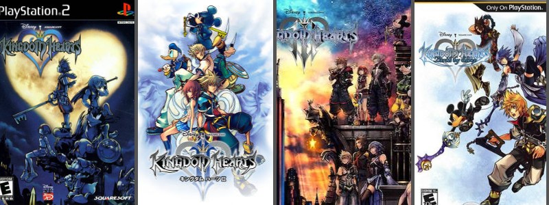
Now that Kingdom Hearts III has finally released, you may be wondering which games are worth playing to help you understand the story. This power-packed action RPG game series showcases a teenage boy named Sora as he navigates a world ruined by creatures called the Heartless. As Sora grasps this new world around him, he […]